Line drawing 2 - Using the Blitter
 Blitter Line Drawing - Amiga Machine Code - Letter XII
The Bresenham line drawing algorithm, was usually implemented in software, but that all changed with the Amiga. The Amiga introduced line drawing in hardware, and if you stick around I’ll show you how it works.
Part 1 of this post discussed the history of the Bresenham algorithm, and retraced the steps to make the algorithm efficient. In Part 2, we continue by taking a look at how the Amiga blitter uses Bresenham’s algorithm.
The Amiga is often praised for it’s innovative hardware design, where special chips provided for much of it’s famous graphic capabilities. Those special chips, where in a sense the precursor for the modern graphic card. Underneath the hood of this machine, inside the blitter, is an implementation of the Bresenham algorithm.
The blitter has a special line-mode, that completely rearanges the meaning of many registers. This dual repurposing of registers can make line-mode a bit confusing.
In line-mode some registers become heavily constrained, like they are only supposed to have one documented value. If you set it to something else, things naturally break apart. It feels almost as if line-mode was bolted on to the blitter, rather late in the design phase.
Enough talk, let’s move on! 😃🚀
The Amiga Way
Line drawing on the Amiga can be done in two ways: Either in software, by using the CPU, or in hardware, by using the blitter.
The blitter excels at drawing pixels. It can draw a million pixels per second, which is an order of magnitude faster than the CPU. The CPU offers more freedom, but the blitter offers more speed.
The blitter has two modes. The first mode, is area mode, deals with moving blocks of data to the screen. The second mode is called line mode, and it enables the blitter to draw lines to the screen.
The Moving Parts
The Amiga Hardware Reference Manual gives a good explaination of how the line mode works. There’s even an overview of the register setup, which comes in handy, since there are quite a few things to set. These references should suffice to get started, but I found them a bit too short on details.
The blitter line mode provides fourteen registers for setting up the line draw. Two of these are BLTCON0 and BLTCON1, which are the control registers, that together control the blitter operations.
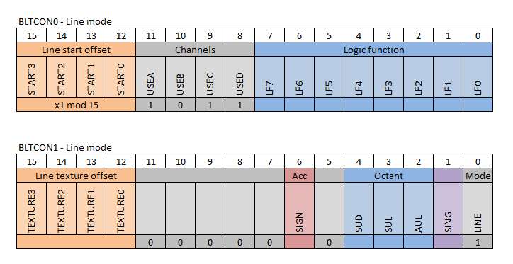
The image above shows the control registers as they look in line mode. They have some mandatory settings for line start, channels and mode, which I’ll explain as we go along.
In order to get startet, the blitter must be put into line mode, by setting register bit 0, also called LINE, in BLTCON1. This changes the meaning of many other registers to something that has to do with line drawing.
If you havent' already, I’ll recommend that you go and read my post about the Bresenham algorithm.
Let’s walk through all the settings.
Setting up the octant
Bresenham’s algorithm uses octants to generalize the line drawing into all directions, by exploiting symmetries along the coordinate axes. This generalization requires the concept of major and minor directions.
The major direction is the direction along the coordinate axis, where the line has it’s largest absolute increment. The minor direction must then be in the direction along the coordinate axis, where the line has it’s smallest absolute increment.
While drawing the line, the Bresenham algorithm always takes a step in the major direction, and sometimes a step in the minor direction.
E.g a line that goes from $(10,10)$ to $(15,8)$ has a major direction of right, and a minor direction of up. Notice that up is opposite the direction of the $y$-axis. Also notice that we always start from the first point, in this case $(10,10)$ and goes towards the second point. That is, the octant is always determined relative to it’s starting point.
The octant is set by the blitter control register BLTCON1, by using the three bits 4, 3, and 2.
- SUD - Sometimes Up or Down
- SUL - Sometimes Up or Left
- AUL - Always Up or Left
The naming of these flags, relates to the minor and major direction.
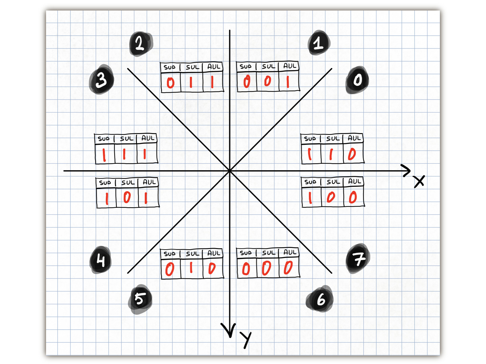
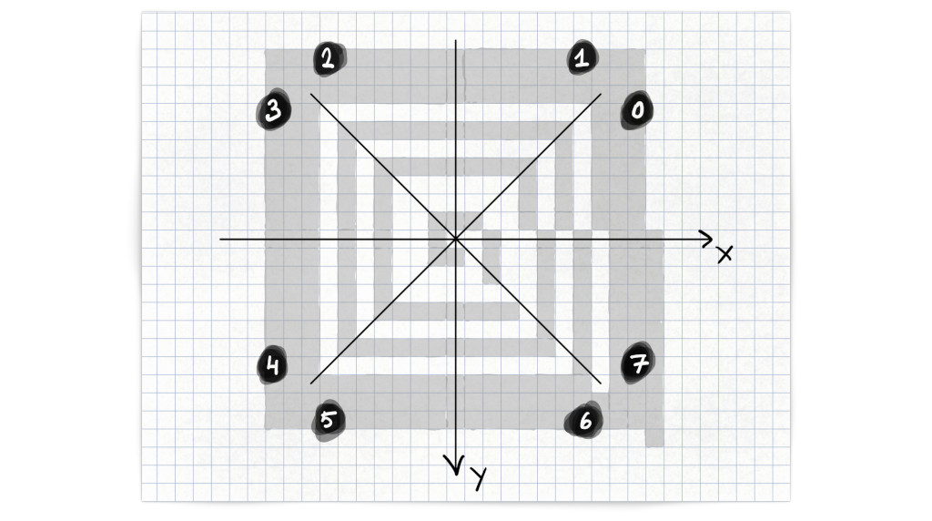
At this point it is good with an overview of how the minor and major directions are assigned in all octants. E.g. if a line is within octant 0, then it’s major direction is right, and it’s minor direction is up. This is illustrated below for all octants.
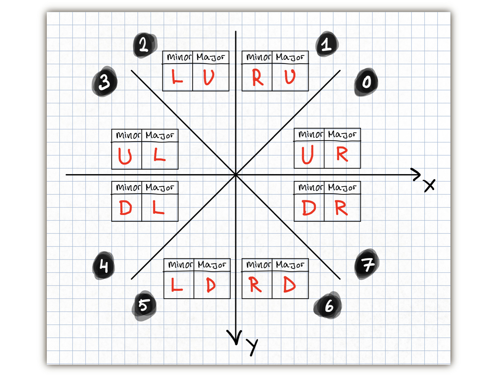
We can expand the major and minor directions into the three bits SUD, SUL, and AUL. The SUD flag, should be set if the minor direction is up or down. The SUL flag, should be set if the minor direction is up or left. The AUL flag should be set if the major direction is up or left. The three flags uniquely identifies the octant.
The line is always drawn between two points. This is also a line segment, that can be defined by it’s increments along the $x$- and $y$-axis, symbolised by $\Delta x$ and $\Delta y$.
The line drawing setup, requires a preparation of $\Delta x$ and $\Delta y$ for the blitter. These values should no longer be viewed as differences along the $x$- and $y$-axis, but differences along the major and minor axis. The value for the major direction is $\Delta x$, and for the minor direction the value is $\Delta y$. Further, both $\Delta x$ and $\Delta y$ should be made positive.
Let’s tie all of this information together into a series of steps, that we later can implement in code.
First, evaluate the inequality: $$|\Delta y | \leq |\Delta x|$$
Set the SUD flag, if the result is true.
If true, then the major direction is along the $x$-axis. If false, then swap $\Delta x$ and $\Delta y$, to ensure that the gradient $a = \frac{\Delta y}{\Delta x}$ never is larger than one.
After this step, $\Delta x$ will be a value along the major direction, and $\Delta y$ will be a value along the minor direction.
Next, evaluate the value along the minor direction:
$$\Delta y < 0$$
Set the SUL flag, if the result is true, and make $\Delta y$ positive.
Last, evaluate the value along the major direction:
$$\Delta x < 0$$
Set the AUL flag, if the result is true and make $\Delta x$ positive.
Another way to look at these steps, is that they have the effect of “normalizing” the line into octant 7.
Example of setting the octant flags:
A line is drawn between $p_1(0,0)$ and $p_2(-2,10)$ and belongs to octant 5.
$$\Delta x = -2, \textrm{ } \Delta y = 10$$
The major direction is found along the $y$-direction.
$$|\Delta y | \leq |\Delta x| \Rightarrow 10 < 2 \Rightarrow \textrm{false}$$
The SUD flag is set to 0, and $\Delta x$ and $\Delta y$ are swapped. By doing this, $\Delta x$ always becomes the major direction, and $\Delta y$ always becomes the minor direction.
$$\Delta x = 10, \textrm{ } \Delta y = -2$$
Next, evaluate the minor direction.
$$\Delta y < 0 \Rightarrow -2 < 0 \Rightarrow \textrm{true}$$
The SUL flag is set to 1. Also remember to make $\Delta y$ positive.
$$\Delta y = 2$$
Finally we evaluate the major direction.
$$\Delta x < 0 \Rightarrow 10 < 0 \Rightarrow \textrm{false}$$
The AUL flag is set to 0. Since $\Delta x$ is already positive, there is nothing more to do.
So to recap, for octant 5 we have:
- SUD = 0
- SUL = 1
- AUL = 0
Try to use the same approach to find the flags for all the octants.
The next part of the line setup, assumes that $\Delta x$ and $\Delta y$ are values along the major and minor direction.
Setting up the accumulator
One of the “tricks” of the Bresenham algorithm, is it’s clever use of an accumulator, that eliminates the need for floating point numbers. The algorithm always takes a step in the major direction, and sometimes takes a step in the minor direction, but only when the accumulator reach a certain value. At this position a pixel is drawn, and the process is repeated for every pixel in the line.
The accumulator setup uses three registers to store the initial value, the increment value, and the decrement value. If the initial value is negative, then the blitter control register BLTCON1 has a SIGN at bit 6, that must be set.
| Description | Register | Address | Expression |
|---|---|---|---|
| initial accumulator value | BLTAPTL | $\$DFF052$ | $4\Delta y-2\Delta x$ |
| accumulator increment without minor step | BTLBMOD | $\$DFF062$ | $4\Delta y$ |
| accumulator decrement with minor step | BLTAMOD | $\$DFF064$ | $4(\Delta y - \Delta x)$ |
All the accumulator expressions are multiplied by two, when compared to the Bresenham alogrithm. We have to do this, because the BLTAPTL register is an adress register, and adress registers can only hold even numbers!
If an uneven number is written to BLTAPTL, then it’s trunctated to a smaller even number. This introduces a small error into the initial accumulator value, that is hard to find – especially if you’re not looking for it. 😱
Because the BLTAPTL is unsigned, we have to use the SIGN bit in BLTCON1 to communicate the sign of the initial accumulator value.
Line-mode changes the meaning of the BLTAPTL register, and I can’t help thinking that it’s a hack that opens the door for bugs. 🐛 🐜
Seting up the Starting Point
The address of the word that contains the first pixel of the line, is given to the blitter through the registers BLTCPT and BLTDPT. Acccording to the register setup both registers should be set to the same adress.
Does this mean that lines can only start on word boundaries, e.g. every sixteenth pixel? No, a line can start anywhere within the word, by using an offset of four bits. The offset is set through the blitter control register BLTCCON0 using bit 12 to 15.
The offset should be set to the lowest four bytes of $x_1$ in the starting point $p_1(x_1, y_1)$. E.g. if $x_1 = \$12$, then the offset should be $\$2$.
The first pixel is written to the address pointed to by BLTDPT, all following pixels are written to the address pointed to by BLTCPT.
This little trick could come in handy, if the first pixel needs to be skipped for some reason. E.g. when drawing polygons. Source.
However, it’s basically a hack, because it’s undocumented. It should be possible to get by without it, by using the correct minterm as we shall see later.
Setting up the Brush
When the blitter draws a line, it uses the brush definition in the BLTADAT register. The brush is 32-bit wide and if a bit is set, then a pixel is drawn.
The register setup says that this brush should always be set to 1 pixel. I.e. we should always preload BLTADAT with $\$8000$. No other value is not supported.
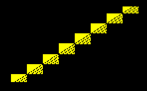
What happens if we try something undocumented like setting BLTADAT to e.g. $\$8888$? 😈
Well, then this happens, with the logic function $D = A$.

I would have expected four lines, since four pixels are set in the brush. But the staircase effect shows that something else is happening.
If we change the logic function to $D = \overline A$, we see the areas that the blitter is working on.
The blitter is word based, which is seen by the 16 bit width of the areas. However, the height of the areas have been optimized for a brush that is only one pixel. Source.
Setting Up the Texture
The blitter can draw a solid or a dashed line by using a texture. The texture is set by preloading BLTBDAT with a 16 bit value. If the line is longer than the texture, then the texture repeats itself, for the length of the line.
To draw a solid line, set BLTBDAT to $\$FFFF$. By changing this value, a wide range of dashed and dotted lines can be drawn.
The start bit of the texture must also be set by using the blitter control register BLTCON1 and setting bits 12-15. These four bits make it possible to provide a start index, between 0 and 15, into the texture.
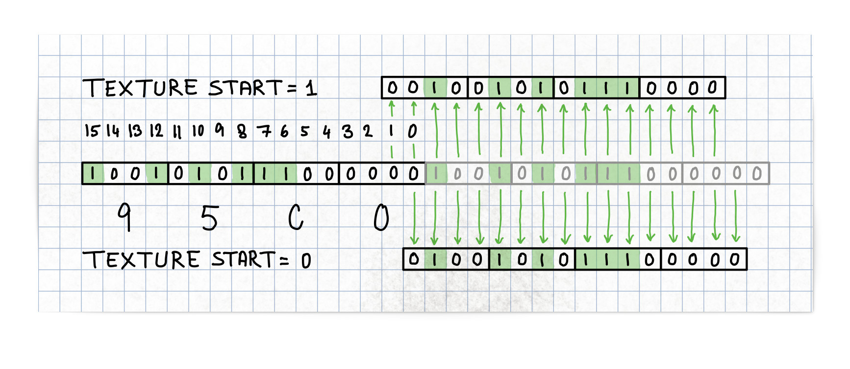
If the texture start bit is set to bit 0, then the texture in BLTBDAT will be applied from bit 0 and then bit 15, 14 and so on. This is also a circular shift right.
Example: We set BLTBDAT to hold the texture $\$95c0$ and set the start texture bit in BLTCON1 to $\$1$. The texture will then start from bit 1, and then bit 0, 15, 14 and so on. This is equivalent of a circular shift of the texture two bits to the right. Those bits that rotate out of the low-order bit go back in at the high-order bit.
$
\begin{split}
Texture &= \$95c0 &= \%1001\ 0101\ 1100\ 0000 \\\
ror(2) &= \$2570 &= \%0010\ 0101\ 0111\ 0000
\end{split}
$
The texture is set for individual lines, and it’s orientation, e.g. horizontal or vertical, is determinend by the octant the line is drawn in. Here’s an example of the texture $\$95c0$ painted in all eight octants, where the texture start is set to zero for all but octant 7, where it’s set to one.
The texture can be seen as mask that blocks or adds line pixels in certain areas. We will dive into this later, when we look at the logic function.
Blitter Channel Setup
The blitter uses input from three source DMA channels $A$, $B$, and $C$, to produce an output to the destination DMA channel $D$.
The blitter has two modes of operation; area mode and line mode.
When the blitter operates in line-mode, the DMA channels will have a special configuration.
- Source DMA channel $A$: Contains the line pixels.
- Source DMA channel $B$: Contains the texture pixels.
- Source DMA channel $C$: Contains the background pixels.
- Destination DMA channel $D$: The destination screen pixels.
Channel $C$ and $D$ points to memory addresses stored in BLTCPT and BLTDPT. As we saw earlier, those two registers should be set to the same address.
Each DMA channel can be independantly turned on and off by using the blitter control register BLTCCON0 bits 8-11. These bits are called USED, USEC, USEB, and USEA.
When the blitter is in line-mode, all but the control bit USEB should be set. By disabling channel $B$, the blitter will use the constant value preloaded into BLTBDAT, and that’s exactly where we have stored the texture value.
According to the Amiga Hardware Reference:
When disabled, no memory cycles will be executed for that channel and, for a source channel, the constant value stored in the data register of that channel will be used for each blitter cycle. For this purpose, each of the three source channels have preloadable data registers, called BLTxDAT.
So to recap, we need to set USEA, USEC, and USED.
The DMA channel $A$, also has a mask for the first and last words along the edges of the rectanglular area that is being blitted. The two masks are set through the registers BLTAFWM and BLTALWM. For line mode, both should be set to $\$FFFF$.
What happens on an Amiga 500, if you don’t obey the documented blitter channel setup? 😈
Clearing bit USEA:
This disables source channel $A$, which stops the accumulator in BLTAPTL from updating. The effect is that only lines along the octant dividers are drawn, because the acccumulator keeps it’s initial value, through the whole blit.
Setting bit USEB:
This should enable source channel $B$, but since line mode does not use BLTBPT, this has no effect.
Clearing bit USEC:
This disables source channel $C$. The effect is that no lines are drawn.
Clearing bit USED:
I expected this would disable destination channel $D$ and thereby any output from the blitter. To my surprise that didn’t happen - line mode works OK without the bit set.
This was inspired by the post: Mysterious world of blitter line mode.
Function Generator Setup
The blitter function generator takes the input from the three source DMA channels $A$, $B$, and $C$ and combine them in various ways, using a boolean function, also provided as an input, that generates an output into the destination DMA channel $D$.
The boolean function is defined by using so-called minterms, that are set by the blitter control register BLTCCON0 bits 0-7.
The register setup specifically mentions two configurations of boolean functions. The normal configuration, with minterm $\$ca$. $$ AB + \overline AC = D$$ And the exclusive-or configuration, with minterm $\$4a$. $$ AB\overline C + \overline AC = D$$
The normal configuration is used when drawing a line on a background, and the exclusive-or configuration is used when a line should only be drawn on areas not filled out by the background.
Let’s walk through both configurations.
We draw a line from $p_1(106,100)$ to $p_2(116,121)$ with a pattern of $\$f0f0$. The patterned line should be drawn upon a stribed bitplane filled with $\$aaaa$ words.
We start with the normal configuration $AB + \overline AC = D$. Let’s unpack it in a series of steps.
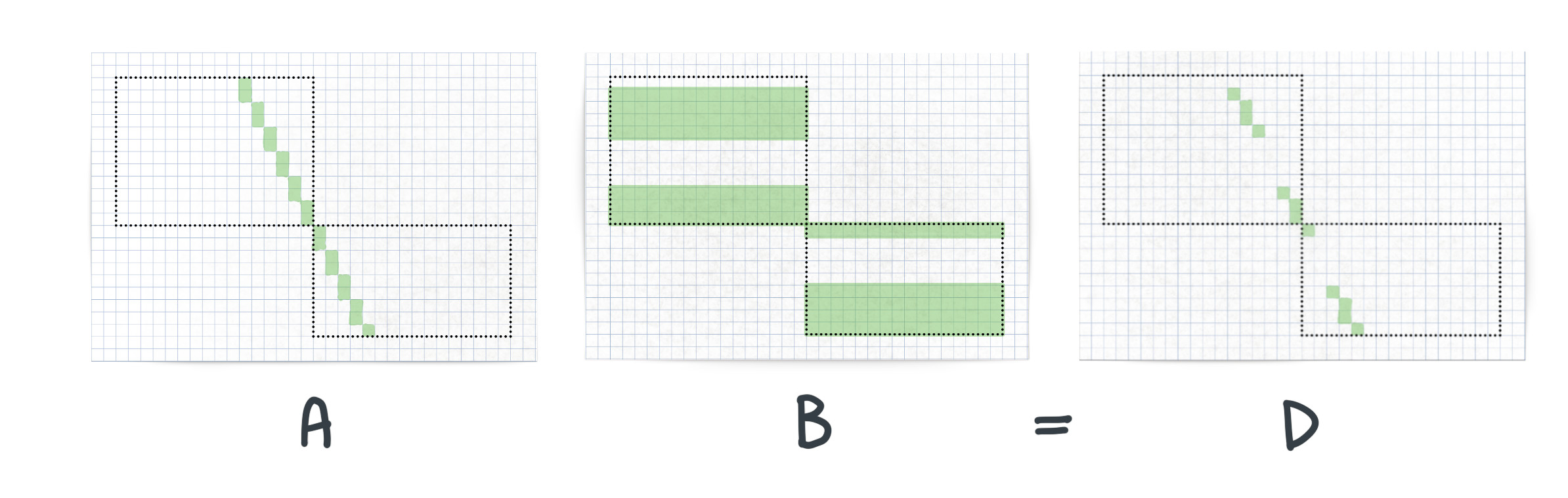
The illustration above shows the minterm $AB = D$ applied. The dotteded bounding boxes show where the blitter operates in memory. When in line mode, the blitter operates on serveral bounding boxes, that have been adapted to fit closely to the line. Otherwise the blitter operates on one bounding box, when in area mode.
The $A$ channel holds the bits for the line drawn by the blitter, and the $B$ channel holds the texture pattern. The result in output channel $D$, is a line with a pattern.
The above illustration shows the minterm $\overline AC = D$. The $A$ channel holds the bits for drawing the inverse line. The $C$ channel contains the background, which will be overwritten, by the blitter, when the result in output $D$ is written to the same memory area as the background. The resulting output $D$ contains the background source and a negative line.
The next illustration, shows the combination of the two previous minterms.
The result in the output from channel $D$ is a line with a pattern, drawn onto the background. I left a few nuances in color on the illustration, but in reality it’s all the same color.
Let’s move on to the exlusive-or configuration $AB\overline C + \overline AC = D$ and see how it is constructed, and what the result is.
The above illustration shows an intermediate step of the exclusive-or configuration. The $AB$ minterm is the line with the texture applied, which is combined with the inverse background $\overline C$ by using an and operation. The resulting output from channel $D$ is the line, with the texture applied, but only in places where there are no background pixels.
The illustration above shows the final step of the exclusive-or configuration. The first term $AB\overline C$ is the result from the previous step, which is combined with the second term $\overline AC$ by using an or operation. The resulting output form channel $D$ is the line, with the texture applied, but only drawn where no pixel exists in $\overline AC$.
Fills
In the BLTCON1 register we also find the SING flag at bit 1. When set, the blitter will output a single line pixel pr. raster line. This is very usefull, when doing fills, like filling a polygon. Exiting stuff for sure, but it have to wait for another post. 🚀
Setup of the Bitplane and Starting the Blit
The width of the bitplane is set by the registers BLTCMOD and BLTDMOD. The register setup in the Amiga Hardware Reference, states that both registers should be set to the same value.
The last register that should be set is BLTSIZE. It should be the last register set, because it triggers the blitter to start the blit.
BLTSIZE is a 16 bit register that contains two fields w and h. Bits 0-5 sets the w field, while bits 6-15 sets the h field. For line mode, w must be set to 2, and h set to the line lenth $\Delta x + 1$.
In the Amiga Machine Code Course they set $h = \Delta x$ in their linedraw routine on disk2. The effect is that the routine will not draw the last line pixel.
I speculate that this choice might make the routine more suitable for drawing polygons? Source.
Next Steps
We have covered a lot of ground in this post, and it’s time to take a break. In Part 3 of this post we are going to look at an Amiga assembler program that does some line drawing. ✏️
Previous post: Amiga Machine Code Letter XII - Line Drawing 1