Amiga Machine Code Letter XII - HAM
 Amiga Machine Code - Letter XII
The Amiga had one of the most photorealistic image modes in the late 80’ties, which could display a massive 4096 colors at the same time - something never seen before in a home computer system. The image mode is called HAM, which is short for Hold and Modify, and if you stick with me, I will tell you what it’s about, and also demonstrate a little assembly program that enables this stuff 🚀.
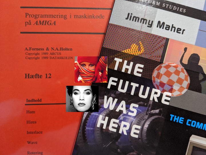
This post is inspired by Letter XII of the Amiga Programming in Machine Code course, and the code I present later is taken from Disk2 from the same course. Now, let’s digg in 👍
Setting the Scene
The Amiga, was the very first multimedia computer for the home, and it was able to provide stereo sound and display photorealistic images. Something like this had not been seen before in the 80’ties and it took the world by storm.
The Amiga is build around planar, rather than chunky graphics. Jay Miner, also known as the father of the Amiga, mentioned this as one of his major Amiga design regrets, in the book The Future Was Here.
Planar graphics uses bitplanes to provide each pixel with a value that maps into a color index. This technique saves memory, because the number of colors in the image depends on the number of bitplanes used. If you only need two colors, then use one bitplane, and if more colors are needed, just add more bitplanes. Using this method, you can reach 32 colors, which uses 5 bitplanes.
Chunky graphics represents pixels with a fixed color depth. The Amiga uses a 12 bit color space, with 16 levels of red, green and blue, and if the Amiga had chunky graphics, each pixel would take up 12 bit of memory regardless of how many colors you really needed. In reality, a chunky system would take up 16 bits per pixel, since each pixel has to be word aligned in memory. Chunky graphics is wasteful, but a powerful simple abstraction.
Since the Amiga used a planar system, with at most 32 color indexes, how on earth was the Amiga able to display 4096 colors at the same time? Well, a trick was required.
Hold And Modify
HAM stands for Hold And Modify, which is very telling for this color mode. One pixel holds a color, and the next pixels along the scanline is then modified one primary color at a time. It can take up to three pixels to arive at the desired color.
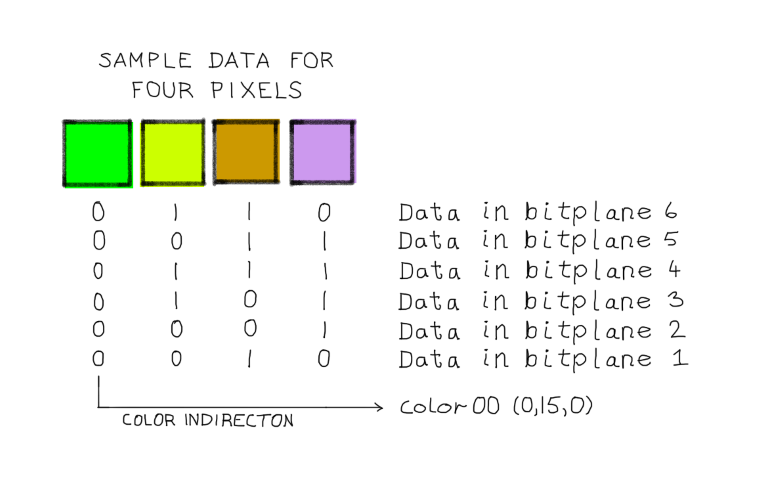
Let’s look at an example. We have an original pixel sequence from 12-bit RGB color, that we want to convert to HAM. In HAM mode we can only convert one primary color in each pixel, so it will take three pixels until we can convert the green color (0,15,0) to the target purplish color (12,9,14).
![]()
Ok, now that we have seen how pixels are modified, then what about the hold color? In the above example, the hold color is the green one, and it’s an index value made by the first four bitplanes, that through color indirection points to one of the first 16 color registers COLORxx. Those colors are also said to be base colors.
Since the colors are modified by starting from a base color, each line in a HAM image must start with a base color. Failing to do that, will not crash the Amiga, but the output will be unpredictable
Let’s take a closer look at the nitty-gritty details. HAM mode requires 6 bitplanes, the first four bitplanes are either color indirection or a modification to the red, green or blue color of the previous pixel. The fifth and sixth bitplanes defines the interpretation of the first four bitplanes, e.g. is it color indirection or a red, green or blue color modification.
- Bitplane 1-4 Color register or color level (0 - 15)
- Bitplane 5-6 Interpretation of bitplane 1-4
The interpretation is:
- If bit 6 and 5 is %00, then bits 1-4 is a color register
- If bit 6 and 5 is %01, then bits 1-4 is a blue color modification
- If bit 6 and 5 is %10, then bits 1-4 is a red color modifictation
- If bit 6 and 5 is %11, then bits 1-4 is a green color modification
Color modification works by first duplicating the color from the pixel to the left to this pixel, and then modifying it. Note that the higher the bitplane, the more significant is the bit.
There exists a modification of the HAM mode, that require only five bitplanes. In this case, the value of the bit from the missing sixth bitplane will be 0.
As we saw in the previous example, it can take up to two intermediate pixels to arive at the desired target color. HAM has this unfortunate side effect, that sharp contrasts along the scanline can cause color fringing - e.g. the colors tend to be smeared. However, one of the insights of image analysis, is that photographic images only rarely change much along a scanline. As we shall see next, this saves the day.
Photorealism and Artifacts
Amiga HAM images with their 4096 colors, brought photorealism within the grasp of ordinary people. But since HAM is a kind of a trick, what kind of artifacts does it introduce?
To answer this question, I needed something to compare the HAM image against, but many of the old Amiga HAM images, came with no original image, so what to do?
I realized that I had to make my own HAM images, so that I could have an original to compare against. The first part of the HAM journey was done by watching this video and the follow up by The Guru Meditation over at Youtube.
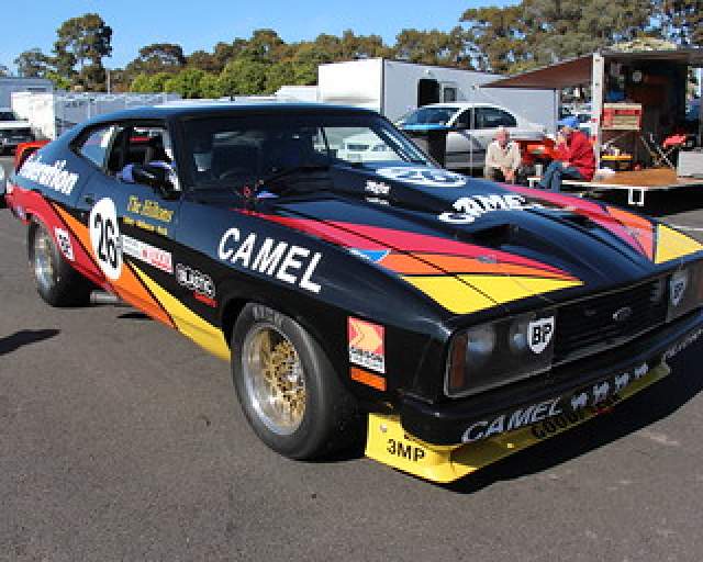
In order to retrace their steps, I first found a suitable image with a lot of contrast, to make the HAM color fringing artifact visible. I found an image of a vintage race car, which had a lot of text on it’s body with high contrast.
The original image was converted from a JPEG to a 24-bit BMP and downsampled to 320*256 to fit an Amiga PAL screen. The image shown below is that BMP converted to a PNG.
Now that I had the BMP, the next step was to fire up Art Department Pro, and convert the BMP to HAM. This required an emulated Amiga 500 with tons of RAM, which back in the day would have costed a small fortune 😃
The image below is the HAM converted image, shown as a PNG, since the browser can’t show HAM nativly. I did not add any dithering of the final output, so it was a clean conversion, and that’s why we see a little color banding on the car body.
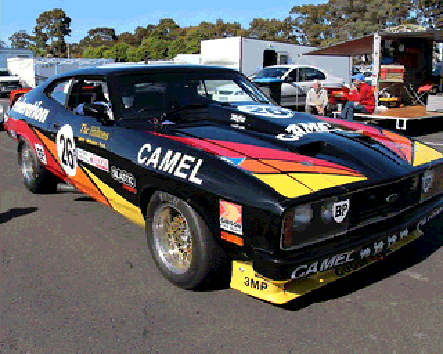
Try to compare the two images of the car. They are almost similar, but notice the color fringing at places with sharp contrasts along the horizontal scanlines. E.g. where the yellow front of the car meets the black letters. Here’s a close-up.
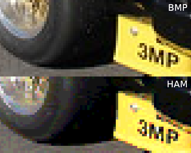
The color fringing is an artifact of HAM only having 16 base colors and, worst case, using two intermediate pixels to reach the desired color. This artifact is especially present in images where there are large horizontal image gradients.
The next image is an animated PNG that switches between the 24-bit BMP image and it’s HAM conversion. There are some differences between the two images, but they are subtle.

Because HAM only rely on 16 base colors, and modifies them to achieve 4096 colors, it can also be viewed as a lossy compression technique, just like JPEG.
When reviewing HAM images, we really should also say something about the display system. You’re propably reading this on an LCD screen, which has a very clear pixel display, compared to the old CRT screens. The pixels on a CRT screen is much more smeared, and it’s actually an effect that makes images look less pixelated compared to LCD screens.
Here’s an example image that shows the same graphics on a CRT, on the left, and a modern display on the right. This CRT artifact made HAM even more photorealistic! 👍
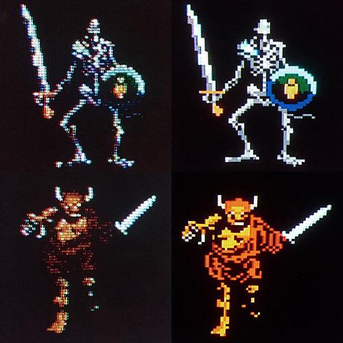
The CRT feel is a big thing in retro gaming, because LCD’s tends to have too sharp pixels. WinUAE also allows for some tweaking of the display, to get closer to that old CRT look. Try to tweak the filter settings, they can really make a huge difference!
Show Me the Code
You can find the code on Disk2 in the ham folder. Read the assembly code into K-Seka and run it by doing these steps.
SEKA>r
FILENAME>ham
SEKA>a
OPTIONS>
No Errors
SEKA>ri
FILENAME>screen
BEGIN>screen
END>
SEKA>j
The next thing the Amiga will do is to serve the HAM image to the display. It looks like this.
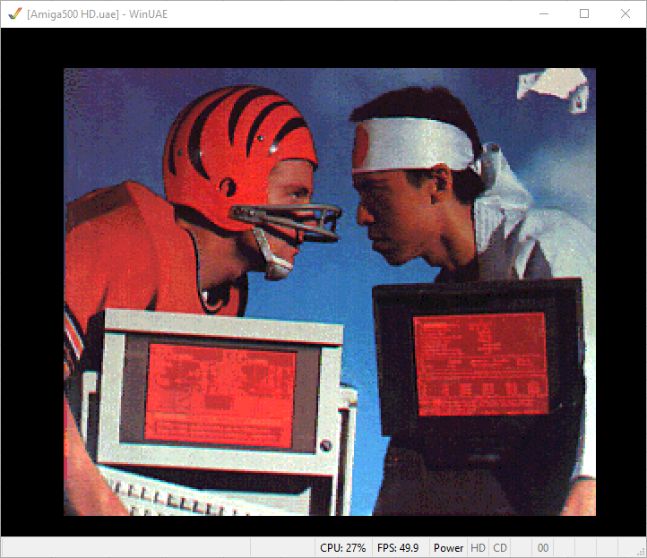
The program assumes that HAM data is already in memory at the screen label. This makes the program simple, since we don’t have to deal with files, and that is why we type in the “ri” command above, to read an image into memory and place it at the label “screen”.
The program works by first disabeling all the interrupts, thus taking over the entire system. Then it reads the first 16 base colors from memory and sets the COLORxx registers accordingly. It then makes a jump of 96 words, to get to the 6 bitplanes, whose addresses are commited to the BPLxPTH/BPLxPTL registers. However, not directly but through the copper list. This makes this program a self modifying program.
The program then setup the copper list and continues to make a busy wait until the left mouse button is pressed. When it’s pressed the program reestablish the workbench copper and exists.
The copper list takes care of setting up the bitplanes, DMA, and the display window.
move.w	#$4000,$dff09a ; INTENA  - disable all interrupts
move.w	#$01a0,$dff096 ; DMACON - disable bitplane, copper, sprite

lea.l	screen(pc),a1  ; move address of screen into a1
move.l	#$dff180,a2    ; move COLOR00 adress into a2
moveq	#15,d0         ; move 15 into d0 (loop counter)
colloop:               ; begin loop that copy the 16 color palette
move.w	(a1)+,(a2)+    ; copy from screen into the color register
dbra	d0,colloop     ; if d0 >= 0 goto collop

lea.l	bplcop+2(pc),a2 ; move address of bplcop + 2 + pc into a2
add.w	#96,a1          ; point a1 to the first bitplane
move.l	a1,d1           ; move a1 into d1
moveq	#5,d0           ; move 5 into d0 (loop counter)
bplloop:                ; Loop over 6 bitplanes and set bitplane pointers
swap	d1
move.w	d1,(a2)         ; set BPLxPTH in bplcop
swap	d1
move.w	d1,4(a2)        ; set BPLxPTL in bplcop
addq.l	#8,a2           ; move to next bitplane pointers in bplcop
add.l	#10240,d1       ; move d1 to point at the next bitplane
dbra	d0,bplloop      ; if d0 >= 0 goto bplloop

lea.l	copper(pc),a1   ; move address of copper into a1
move.l	a1,$dff080      ; set COP1LCH and COP1LCL to address of a1

move.w	#$8180,$dff096  ; DMACON - enable bitplane, copper

wait:
btst	#6,$bfe001      ; busy wait until left mouse button is pressed
bne.s	wait

move.l	$04.w,a6        ; make a6 point to ExecBase of exec.library, which is also a struct
move.l	156(a6),a6      ; IVBLIT points to GfxBase
move.l	38(a6),$dff080  ; copinit ptr to copper start up list restore workbench copperlist

move.w	#$8020,$dff096  ; DMACON - enable sprite
rts                     ; return from subroutine

copper:
dc.w	$2001,$fffe  ; wait($01,$20)
dc.w	$0102,$0000  ; move $0000 to $dff102 BPLCON1 scroll
dc.w	$0104,$0000  ; move $0000 to $dff104 BPLCON2 video
dc.w	$0108,$0000  ; move $0000 to $dff108 BPL1MOD modulus odd planes
dc.w	$010a,$0000  ; move $0000 to $dff10a BPL2MOD modulus even planes
dc.w	$008e,$2c81  ; move $2c81 to $dff08e DIWSTRT upper left corner ($81,$2c)
dc.w	$0090,$f4c1  ; move $f4c1 to $dff090 DIWSTOP (enable PAL trick)
dc.w	$0090,$38c1  ; move $38c1 to $dff090 DIWSTOP (PAL trick) lower right corner ($1c1,$12c)
dc.w	$0092,$0038  ; move $0038 to $dff092 DDFSTRT data fetch start at $38
dc.w	$0094,$00d0  ; move $00d0 to $dff094 DDFSTOP data fetch stop at $d0

dc.w	$2c01,$fffe  ; wait($01,$2c)
dc.w	$0100,$6a00  ; move $6a00 to $dff100 BPLCON0 - use 6 bitplanes, HAM, enable color burst

bplcop:
dc.w	$00e0,$0000  ; BPL1PTH
dc.w	$00e2,$0000  ; BPL1PTL
dc.w	$00e4,$0000  ; BPL2PTH
dc.w	$00e6,$0000  ; BPL2PTL
dc.w	$00e8,$0000  ; BPL3PTH
dc.w	$00ea,$0000  ; BPL3PTL
dc.w	$00ec,$0000  ; BPL4PTH
dc.w	$00ee,$0000  ; BPL4PTL
dc.w	$00f0,$0000  ; BPL5PTH
dc.w	$00f2,$0000  ; BPL5PTL
dc.w	$00f4,$0000  ; BPL6PTH
dc.w	$00f6,$0000  ; BPL6PTL

dc.w	$ffdf,$fffe  ; wait($df,$ff) - enables waits > $ff vertical
dc.w	$2c01,$fffe  ; wait($01,$2c) - $2c is $12c
dc.w	$0100,$0a00  ; move $0a00 to $dff100 BPLCON0 - HAM, enable color burst
dc.w	$ffff,$fffe  ; end of copper list

screen:
blk.w	61568/2,0 ; allocate (320*256 pixels * 6 bitplanes) / 8 + 128 bytes = 61.568 bytes
As I mentioned earlier, a special HAM mode exists, that require only five bitplanes. The bit from the missing sixth bitplane will be set to 0, and that totally screws with the color modifiers. With the sixth bit set to 0, one can only modify the blue color, and I wonder if that’s useful at all.
You can try out this five bitplane HAM mode by changing this line in the copper list
dc.w $0100,$6a00 ; move $6a00 to $dff100 BPLCON0 - use 6 bitplanes
to this
dc.w $0100,$5a00 ; move $5a00 to $dff100 BPLCON0 - use 5 bitplanes
But I warn you, it doesn’t look pretty. Especially since the image wasn’t designed for five bitplanes.
HAM Mode in Games
HAM mode was not used in games for anything more than still images, which could be title images or images that are displayed between levels.
The reason HAM wasn’t used much for ingame animation, was that BOB’s when moved around on the screen, were very likely to introduce color fringing. In a still image some color fringing is acceptable, but in a dynamic moving scene, it can quickly become anoying.
There’s a great discussion over at stackexchange about HAM in games. It’s from there that I have found the two following games that’s using ingame HAM mode!
Both games works by having backgrounds that are within the first 16 base colors present in the color table. They then blit BOB’s onto the screen that are in modified colors. Also notice the thick black outline around the BOB’s, which are there to prevent color fringing from the background pixels.
Pioneer Plague, was the first game for the Amiga that used ingame HAM mode, and it was made by Bill Williams.
Knights of the Crystallion, was also made by Bill Williams, and it was his final game for the Amiga platform.
HAM mode never became a success for ingame action, but that does not mean that HAM mode was a failure. As we shall see next, it completely created a new scene for digitized images.
HAM Mode and Video Digitizing
A couple of months after the Amiga appeared in stores in 1985, the first photorealistic images began to circulate. The images was not just stunning, but a hint of a revolution to come. These images was made possible by the HAM mode, a happy accident, that Jay Miner intended to remove from the Amiga. You can read about it in the book The Future Was Here.
Many people had their first enconter with the photorealistic HAM images, by seeing the NewTek Demo Reel from 1987. It was by todays standard, more or less, a slideshow of the wildest images seen on a home computer system.
The Demo Reel starts of with Maxine Headroom, whose real name is Laura Longfellow, a NewTek employee. This was a tribute to the fictional character Max Headroom, an artificial TV host of the 80’ties.
When I first saw the demo reel in the 80’ties, I was completely blown away. I had just moved from an 8-bit ZX Spectrum to the Amiga 500, so this was WILDEST thing ever!
One of the first affordable systems for digitizing color images, was Digi-View from NewTek. This system uses a video signal to scan a still image and requires a black and white video camera and a color filter wheel with transparent, red, green and blue filters. The recorded image was then scanned through the colored filters and combined to a color image by the Amiga. The transparent filter was for black and white images.
The system digitized the image one pixel column at a time. Digitizing a 320*200 (NTSC) image required (320 / 30 frames pr. second) = 10.67 seconds. For a color image, each color channels had to be digitized, which in total required 32 seconds. Any movement or change in lighting during this process would ruin the result.
The Digi-View system was easy to operate but required a careful setup of camera fixture and lighting. Here’s a video showing the process.
The digitized image could then later be brushed up in Digi-Paint - a paint program that could paint and edit HAM images.
An interesting side story is that Dan Silva - creator of Deluxe Paint - did not let his program support HAM mode. HAM support was added to Deluxe Paint IV, after Dan Silva had left Electronic Arts.
The image below, shows my attempt at drawing a HAM image in Digi-Paint. Notice the color palette only have 16 colors. Those are the base colors we talked about before. The image to the left, is drawn using only the base colors. The image to the right, is with the added green and blue colors. Since neither green or blue is in the palette, the desired colors have to be reached by modifying pixel colors, and that causes some color fringing. You might have to zoom to see it.

The example above, shows that HAM mode is not an obvious choice for hand drawn images, unless you are careful about color fringing. Programs, such as Digi-Paint, are much more suited for editing digitized photos, because of their often small horizontal image gradients. Perhaps that’s why Dan Silva did not prioritize HAM mode for Deluxe Paint?
The video below, shows how to use Digi-Paint and also go into much more detail about the color fringing issues and free hand drawing. It’s also a good primer, if you want to learn how to use Digi-Paint.
NewTek has since left it’s Amiga origins. The products they made back in the Amiga days have left a huge imprint on the company to this day. They are still doing video editing with the TriCaster system, and also upgrading LightWave 3D.
We have come a long way on this HAM mode journey. I hope you enjoyed reading it, as much as I did writting it. Next up, is the highres mode of the Amiga 😃 👍.
Previous post: Amiga Machine Code Letter XI - Printing.
Next post: Amiga Machine Code Letter XII - Vertical Scalling Using the Copper